Honda CR-V: Auto-tensioner Removal and Installation
Removal
1. Remove the chain case cover.

2. Turn the crankshaft counterclockwise to compress the auto-tensioner.
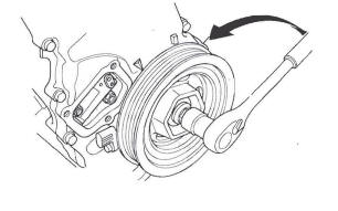
3. Align the holes on the lock (A) and the auto-tensioner (B), then insert a 1.2 mm (0.05 in.) diameter pin or lock pin (P/N 14511 -PNA-003) (C) into the holes. Turn the crankshaft clockwise to secure the pin.

4. Remove the auto-tensioner.

Installation
1. Install the auto-tensioner.

2. Remove the pin or lock pin (P/N 1451 1-PNA-003) from the auto-tensioner.

3. Remove old liquid gasket from the chain case cover mating surfaces, bolts, and bolt holes.
4. Clean and dry the chain case cover mating surfaces.
5. Apply liquid gasket, P/N 08717-0004,08718-0001, 08718-0003, or 08718-0009, evenly to the chain case mating surface of the chain case cover. Install the component within 5 minutes of applying the liquid gasket.
NOTE:
- If you apply liquid gasket P/N 08718-0012, the component must be installed within 4 minutes.
- If too much time has passed after applying the liquid gasket, remove the old liquid gasket and residue, then reapply new liquid gasket.

6. Install the chain case cover.
NOTE:
- Wait at least 30 minutes before filling the engine with oil.
- Do not run the engine for at least 3 hours after installing the chain case cover.

Chain Case Oil Seal Installation
Special Tools Required
- Driver 07749-0010000
- Attachment, 52 x 55 mm 077 46-0010400
1. Use the driver and attachment to drive a new oil seal squarely into the chain case to the specified installed height.

2. Measure the distance between the chain case surface and oil seal.
Oil Seal Installed Height: 33.0-33.7 mm (1.30-1.33 in.)

READ NEXT:
 Cam Chain Inspection
1. Remove the front wheels.
2. Remove the splash shield (see step 21).
3. Remove the drive belt.
4. Remove the cylinder head cover.
5. Set the No.1 piston at top dead center (TDC). The
punch mark
CKP Pulse Plate Replacement
1. Remove the front wheels.
2. Remove the splash shield (see step 21).
3. Remove the drive belt.
4. Remove the cylinder head cover.
5. Set the No.1 piston at top dead center (TDC). The
punch mark
Cylinder Head Cover Removal/Installation
Cylinder Head Cover Removal
1. Remove the intake manifold cover.
2. Remove the four ignition coils.
3. Disconnect the evaporative emission (EVAP)
canister purge valve connector.
4. Remove the dipst
SEE MORE:
Vehicle Stability Assist (VSA ), aka Electronic Stability Control (ESC),
System
The vehicle stability assist (VSA)
system helps to stabilize the vehicle
during cornering if the vehicle turns
more or less than desired. It also
assists you in maintaining traction
while accelerating on loose or
slippery road surfaces. It does this
by regulating the engine’s output
Navigation Unit Removal/Installation
SRS components are located in this area. Review the SRS component location.
Also review the precautions and procedures in the SRS section before doing repairs or
service.
NOTE:
Put on gloves to protect your hands.
Take care not to scratch the dashboard and related
parts.
Lay a workshop towel u
